Isometric Tiles in Blender
In this tutorial we will create pre-rendered Isometric tiles for use in 2D games. This tutorial uses Blender version 2.6.
Note that this isn't true Engineering isometric where each angle is 60 degrees. In pixel-based video games we get cleaner diagonal lines by using a slightly different projection.
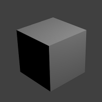 The default scene in Blender looks like this. Just a plain cube with a single point lamp.
Orthographic Camera
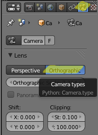 The first thing we want to do is switch to an Orthographic camera. Right-click to select the camera in 3D view. Then, click the Camera icon in the Properties panel. Under the "Lens" section, choose Orthographic.
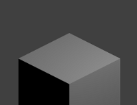
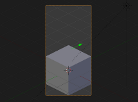
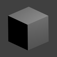 In the result you'll see our cube is now in the correct perspective. In isometric games, lines perpendicular to the ground plane should appear parallel to each other. Put another way, Orthographic means objects further away do not appear smaller.
Isometric Camera Angle
 Next up, we want to set the camera angle for perfect isometric mode. In video games when we say "isometric" we usually mean that the base tile size is exactly 2x as wide as it are tall (e.g. 64x32). While the camera is still selected and with the cursor over the 3D viewport, hit "N" to show object properties.
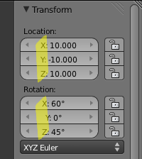
The Rotation settings are RotX = 60, RotY = 0, RotZ = 45. And while we're there, let's put the camera in a predictable location: LocX = 10, LocY = -10, LocZ = 10.
Once these are set, you can hit N again to close the transform properties window.
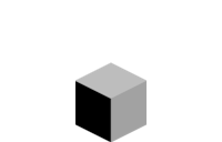
 What does this camera angle do? If you measure the top of this rendered cube, you can verify that the pixel width is exactly twice the pixel height.
Render Size
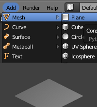 We want our render output to be exactly the correct size for use in a game. It's easier if we start with a simple floor tile. First, remove the Cube by right-clicking and pressing Delete. Then using the top menu: Add -> Mesh -> Plane.
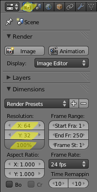 Let's change the Render size. In the Properties area switch to the Render pane. Under the Dimensions section, change Resolution to X: 64 and Y: 32 and the Scale to 100%.
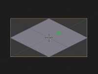
 The render output will now be correctly sized at 64x32 pixels, but the plane is off-center and too small.
Camera Location Z and Orthographic Scale
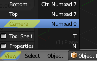 Now we tweak the camera until the tile fits the output area. In the 3D viewport, change to Camera view by pressing Numpad 0 or clicking View -> Camera.
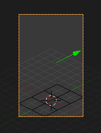
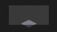 The 3D viewport now looks like this. Everything inside the dashed line is what the camera sees. Everything outside the dashed line is darkened and is outside the camera's view. Make sure the Camera is the selected object -- do this by right-clicking the dashed outline of our camera's view in 3D (the outline will glow).
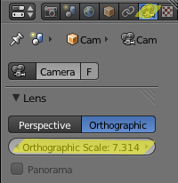 Open the Camera Properties again (Properties menu, click the Camera) and notice the Orthographic Scale value.
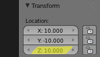 Open the Transform Properties panel again (N-key in 3D view) and notice the Location: Z value.
 Tweak these two values until the tile takes up the entire render area. Orthographic Scale changes the "zoom" and Location Z changes the vertical position. I change the Orthographic Scale first until the tile is the correct width, then change Location Z until it is centered vertically. Here I use Orthographic Scale: 2.800, Location Z: 8.170
Hint: it's better for the tile to overflow slightly than to be too small. This helps prevent translucent seams between tiles.
 Now our pane is rendered at the correct size!
Transparency
![]() Our tiles won't work well with that opaque background. Here's how to set up a transparent background. In the Properties panel, switch to the Render section. Under Output change to RGBA (only available in certain formats, e.g. PNG).
Our tiles won't work well with that opaque background. Here's how to set up a transparent background. In the Properties panel, switch to the Render section. Under Output change to RGBA (only available in certain formats, e.g. PNG).
Under Shading switch Alpha Mode from Sky to Straight Alpha. Without this, your tile's translucent edges will have the color of your 3D sky (usually causing visible seams).
![]() Now our render has correct transparency.
Now our render has correct transparency.
Lighting
 If you look closely at our tile you'll see that the left side is darker than the right. This is because Point lamps are dimmer the further they are away. We want to use lights that aren't affected by distance, such as Sun lamps.
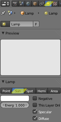
In the 3D viewport switch to Top view (Numpad 7 or View -> Top). Select the Lamp (right-click). In the Properties menu, click the Lamp button (where the Camera was before). Change the Lamp type from Point to Sun.
 Now our tile is evenly lit. Usually you'll want all your tiles to use the same set of lights so that the angles of highlights and shadows are consistent.
Click here to download this .blend file
Tall Tiles
 Not all of your tiles will be floor-shaped (64x32 here). You'll want tall tiles that sit over the floor. Here we're going to create a Cube tile. I deleted the Plane and added a Cube (making sure that it's positioned at the origin). I changed the output resolution from 64x32 to 64x128. Now I change the camera's Location Z and Orthographic Scale again. If your object is sitting above the floor, you want to position it at the bottom of the camera's view. Here I use Orthographic Scale: 5.600, Location Z: 9.600.
 Here is the tall tile output. There is a bit of unused space above the cube, but for most cases it's best to keep your tile dimensions at powers of 2 (e.g. 16, 32, 64, 128, 256, 512).
Oversized Tiles
 Tiles that span multiple grid spaces can be created with just a couple extra steps. Let's say I want to create a tall building that occupies a 2x3 tile area, and I calculate that the tile should be 160x256 pixels. First, set the render output to the desired 160x256. Next, create a "guide" plane that occupies the 2x3 tile area. Move the plane so that it is centered on the origin (we want to position the tile instead of changing the camera's Location X,Y).
Now, simply tweak the camera's Orthographic Scale and Location Z just as if you were creating a tall tile. Fit your guide plane to the left + right + bottom of the camera's view. Now your output will correctly capture this 2x3 tall tile.
Tips and Tricks
The above will get you most of the way there. Here are some additional hints that may save you some trouble later.
- Set up a blank Blender scene that contains your isometric cameras, lights, etc. Use it as your starting point when creating new tiles.
- It helps to choose a fixed scale for your tiles. I prefer to use 1 blender unit = 1 meter, and 1 tile = 1 square meter. That way you can keep all your assets at the same scale.
- You might want to include casted shadows for tall tiles. Create a large plane at Z=0 to catch shadows. Give it a material with Shadow -> "Shadows Only" enabled. I also set the material's Transparency -> Alpha to 0.500 for translucent shadows.
- If you're rendering a large number of tiles, it's easy to pull them together into a single tileset image with the ImageMagick tool "montage".
- To get finer details in your render (possibly at the expense of noise), change the Anti-Aliasing size of Mitchell-Netravali from 1.000 to 1.500
- I use guide planes often when working with multiple tiles. See an example in Oversized Tiles, above. I create these by copying a plane and deleting Faces Only (leaving the edges). Now the grid squares are visible even when the guide plane isn't selected. And they are invisible in renders because they have no faces.
Addendum: Render script
I want some objects to have sprites facing 8 different directions (up/down/left/right and diagonals). This script will render the current Animation for each direction. It works by having an Empty object renamed to "RenderPlatform", with any rotating objects parented to it (usually lights and camera).
import bpy
from math import radians

angle = -45
axis = 2 # z-axis
platform = bpy.data.objects["RenderPlatform"]
original_path = bpy.data.scenes[0].render.filepath

for i in range(0,8):

    # rotate the render platform and all children
    temp_rot = platform.rotation_euler
    temp_rot[axis] = temp_rot[axis] - radians(angle)
    platform.rotation_euler = temp_rot;

    # set the filename direction prefix
    bpy.data.scenes[0].render.filepath = original_path + str(i)

    # render animation for this direction
    bpy.ops.render.render(animation=True)

bpy.data.scenes[0].render.filepath = original_path
About the Author
 Clint Bellanger is a software developer who has been experimenting with video game code for 30 years and 3D art for 20 years. His latest project is Flare, a Free/Libre action roleplaying engine.